Nice to see you're putting two throttle bodies on too

________________________________________
www.bridgecraftmotorsport.co.uk


|
| Author | Subject: Goldie the track car |
 allanallen allanallen
Seasoned Pro Location: Buxton Registered: 01 May 2007 Posts: 1,399 Status: Offline |
Post #526
Ally welding looks good Steve! Knew you'd suss it!Nice to see you're putting two throttle bodies on too  ________________________________________ www.bridgecraftmotorsport.co.uk |
|
|
|
 Nick.gti6 Nick.gti6
Regular Location: Newport Registered: 22 Aug 2013 Posts: 242 Status: Offline |
Post #527
You going to fcs mate? |
|
|
|
 prism7guy prism7guy
Seasoned Pro Location: DoncastAAAAARGH Registered: 13 Jan 2008 Posts: 4,640 Status: Offline |
Post #528
eddy_gti6 wrote: Nice bit progress there. Looking well and good work on the fabrication parts  Cheers Chris. luke306rallye wrote: Awesome work Steve, you need to make bits for mine.  Thanks Luke, not sure i'll be allowed in the workshop too much for a while, got to let the boss forget how much time i've been spending in there out of hours  allanallen wrote: Ally welding looks good Steve! Knew you'd suss it! Nice to see you're putting two throttle bodies on too  Thanks Allan, my very first attempt was horrendous, so i got some thicker electrodes and filler wire and gave it a go on the flange. Luckily it worked out well, can't believe how much faster you have to work with it though compared to mild! And yeah, i thought it would be a good idea to follow your advice on the twin throttle body setup after you told me about yours. How did you go about having two throttle cables, just run two from the pedal or have like a take-off from one body to the other? Nick.gti6 wrote: You going to fcs mate? I won't be at fcs this year, i'll be at Pugfest though.  ________________________________________ Goldie the track car. |
|
|
|
 allanallen allanallen
Seasoned Pro Location: Buxton Registered: 01 May 2007 Posts: 1,399 Status: Offline |
Post #529
Yeah you've got be quick with ally! Like you say, big electrode with a rounded end and thick filler. I'm pretty crap at welding ally! Re throttle cables, I made a cable stop that holds two cables in the bulkhead and then a clamp arrangement on the pedal to pull the two inners. Basically just a bolt with holes through 'a la' push bike stylee! Pedals pretty stiff now, I'm gonna remove one of the springs from the throttle on the charger. Are you using 2 gti6 throttles? Mine are both Volvo v70 items, I bored the ramps out of the charger throttle body though so it's just a pretty much straight bore, left the one on the inlet mani as it helps with low revs drive ability I find  ________________________________________ www.bridgecraftmotorsport.co.uk |
|
|
|
 rallyeash rallyeash
Seasoned Pro Location: Devizes Registered: 11 Dec 2006 Posts: 4,424 Status: Offline |
Post #530
Why two throttle bodies? Not seen that before. ________________________________________ 230 hp 2.1 16v XU 205 rallye on jenveys Project thread here Project thread here309 3dr K20 Type R |
|
|
|
 allanallen allanallen
Seasoned Pro Location: Buxton Registered: 01 May 2007 Posts: 1,399 Status: Offline |
Post #531
It's pretty common on mx5 and Honda conversions. Throttle in standard pos for better throttle response and ease of mapping, second throttle to stop the charger backing up with boost when you let the throttle off at 7k, it's easy to stall them and it soon destroys them. Without a second throttle body you need a high flowing re-circ valve or a big dump valve. I used to run 2 dump valves and it still wasn't brilliant! It's loads better with the second body, just a quick chirp from the single dump valve when you let off then the charger goes into vacuum.Drives nicer, quieter on part throttle and tickover, it's all good! ________________________________________ www.bridgecraftmotorsport.co.uk |
|
|
|
 prism7guy prism7guy
Seasoned Pro Location: DoncastAAAAARGH Registered: 13 Jan 2008 Posts: 4,640 Status: Offline |
Post #532
That sounds like a good idea Allan, i was thinking of making like a bracket which holds the cable from the throttle pedal one end, then a double adapter to connect that cable to the two that will go to the two throttle bodies, and have them so they are in like a threaded union so theres some small amount of adjustability which should allow me to fine tune the 'charger's throttle body whilst at idle.Yeah i will be using two gti6 throttles, mainly because i have a couple of spare and i've got to watch how much money i'm currently throwing at the project  I'm in two minds whether to have the 'charger outlet flange use a 2.5" or 3" outlet. I'm sure the 3" would probably be slightly better in terms of flow then have it go into a reducer down to 2.5" for the intercooler, but space is kind of tight in that area with the radiator and slam panel, i'm sure the slam panel is going to need some fettling regardless. Would you go for the 2.5" or 3"? The laminova arrived today, i'm going to get the oil lines and fittings ordered in a minute so i can start dry plumbing it all in to see how it's all going to fit. One other question i wanted to ask, i'm going to get a header tank, from what i've read the main outlet wants to go to the area of lowest pressure which will be just before the pump, does it matter if it goes into the bottom radiator hose, or that small hose that runs along the back of the block? My radiator also has a bung in the end tank just above the bottom outlet, i was considering using a banjo fitting in that to have the main outlet run into. Also, for return, would there be any problem with fitting a banjo into the m6 thermostat bleed point and having that return back to the header tank? That should be the highest point in the system as far as i can see. EDIT: Also, did you use a recirc dump valve or just an atmospheric one for your twin throttles? I was thinking of doing a recirc so theres not really a vacuum or boost that the charger has to put up with when the throttles are closed. ________________________________________ Goldie the track car. |
|
|
|
 rallyeash rallyeash
Seasoned Pro Location: Devizes Registered: 11 Dec 2006 Posts: 4,424 Status: Offline |
Post #533
allanallen wrote: It's pretty common on mx5 and Honda conversions. Throttle in standard pos for better throttle response and ease of mapping, second throttle to stop the charger backing up with boost when you let the throttle off at 7k, it's easy to stall them and it soon destroys them. Without a second throttle body you need a high flowing re-circ valve or a big dump valve. I used to run 2 dump valves and it still wasn't brilliant! It's loads better with the second body, just a quick chirp from the single dump valve when you let off then the charger goes into vacuum. Drives nicer, quieter on part throttle and tickover, it's all good! Makes sense. Just not come across it. But then I've never had much to do with charged engines before. ________________________________________ 230 hp 2.1 16v XU 205 rallye on jenveys Project thread here Project thread here309 3dr K20 Type R |
|
|
|
 allanallen allanallen
Seasoned Pro Location: Buxton Registered: 01 May 2007 Posts: 1,399 Status: Offline |
Post #534
Mine uses 2.25 piping, I'd imagine 2.5 will be plenty big enough for what the charger will flow/pressure.Header filler can indeed go to the small outlet on the rear water distribution block. The self bleeder from the t-stat housing to the header tank, that's how I do gti6s in 205s, it's essentially how the 205gti/mi16 was piped as standard  I run an atmospheric dump valve, when I say the charger runs a vacuum it's nowt serious, not even enough to suck the silicone hoses in. ________________________________________ www.bridgecraftmotorsport.co.uk |
|
|
|
 prism7guy prism7guy
Seasoned Pro Location: DoncastAAAAARGH Registered: 13 Jan 2008 Posts: 4,640 Status: Offline |
Post #535
Made a little more progress this week, had a few new shiny bits turn up too, and some more bits finished at the laser cutters.  Just want to say a big thanks to Allan for loads of advice he keeps giving me  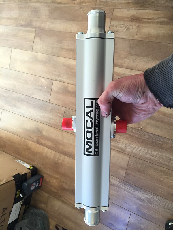 IMG_4671 by Steve Count, on Flickr IMG_4671 by Steve Count, on FlickrHopefully that will be up to the job of controlling oil temps! Drilled out and tapped the oil take off plate, it's now 1/2" bsp and has some proper adapters to an10. I tried doing the same to the oil filter relocation part but i drilled a little too far and broke through the wall between the inlet/outlet so essentially turned it into scrap. Not to worry though as i bought a proper jobby from torques, much better design. Only down side to that was it only came with 3/4" UNF fittings for the oil filter, i wanted to keep it m20x1.5 to suit regular filters so i made an adapter at work. I had to fettle the 'charger mounting plate to accommodate the size of the an10 fittings, not too much of an issue though i don't think.  IMG_4695 by Steve Count, on Flickr IMG_4695 by Steve Count, on Flickr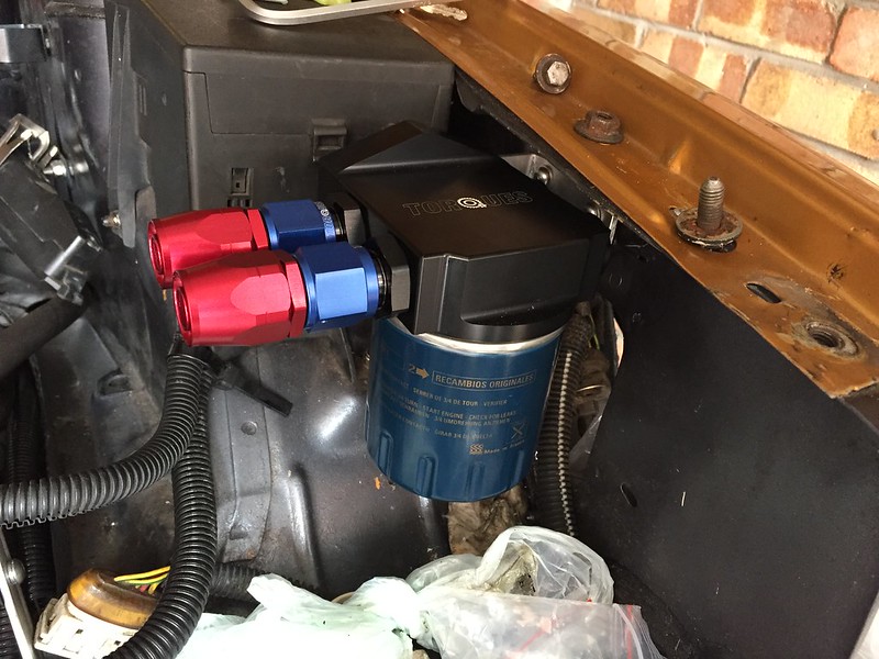 IMG_4851 by Steve Count, on Flickr IMG_4851 by Steve Count, on FlickrI made an outlet for the 'charger 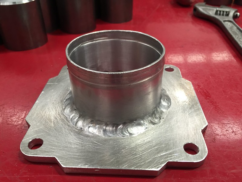 IMG_4692 by Steve Count, on Flickr IMG_4692 by Steve Count, on Flickr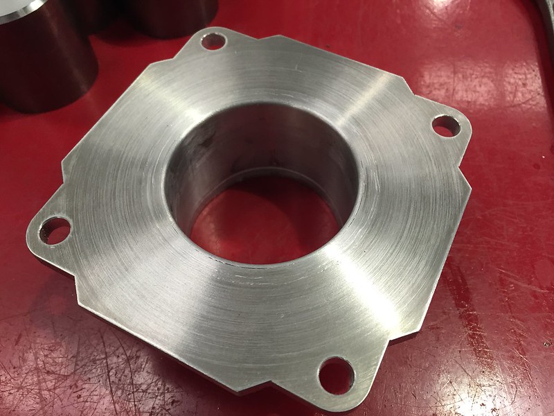 IMG_4693 by Steve Count, on Flickr IMG_4693 by Steve Count, on FlickrAlso made an adapter to suit a standard throttle body so it can fit a 3" hose to it, this will bolt to a throttle body just before the 'charger inlet.  IMG_4713 by Steve Count, on Flickr IMG_4713 by Steve Count, on Flickr IMG_4842 by Steve Count, on Flickr IMG_4842 by Steve Count, on FlickrFitted a bbm adapter plate and the top hose flange from a 205 to do away with the daft normal top hose fitting.  IMG_4700 by Steve Count, on Flickr IMG_4700 by Steve Count, on FlickrThe Direnza radiator i got didn't come with any way of easily securing it at the top, i'm using the old radiators rubber mounts at the bottom so i knocked up some ally bits at work to make mounting it a bit easier, and welded them on.  IMG_4702 by Steve Count, on Flickr IMG_4702 by Steve Count, on FlickrAnd the radiator mounted, using rubber bobbins to stop any vibrations upsetting anything.  IMG_4715 by Steve Count, on Flickr IMG_4715 by Steve Count, on FlickrI started mocking up and some basic work on a new manifold, i was hoping to use a standard one but there was clearance issues with the 'charger, so i'm going to use an old manifold i chopped down with the intentions of fitting ITB's. Had a new backplate laser cut which is visible in the below picture. I've drilled and tapped a few holes in this plate to allow me connect the fuel pressure regulator, a dump valve and a map sensor. I've bought a 2.5 bar magneti marelli one, can't see me ever getting close to 1.5 bar above atmospheric so this should be more than up to the job, and was a fair bit cheaper than a 3 bar equivalent. 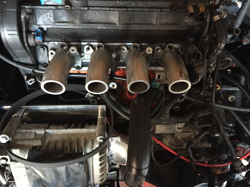 IMG_4672 by Steve Count, on Flickr IMG_4672 by Steve Count, on FlickrThe offside end of the manifold will house the idle control valve. Here it is as it stands.  IMG_4733 by Steve Count, on Flickr IMG_4733 by Steve Count, on Flickr IMG_4764 by Steve Count, on Flickr IMG_4764 by Steve Count, on FlickrBefore i can really crack on with the manifold i'm going to turn some small trumpets which will be welded on the inside of the back flange, hopefully it will mean air flows nicely down each runner. The manifold will be 4"x4" so should be plenty big enough for reasonable air distribution, i did think about tapering it but decided it would make it too easy to mess up  The final job of today was to sort out a header tank. I've seen a few on ebay but only one seemed like it would fit where i wanted it, the seller said he could fit custom outlet sizes so i sent him a message, waited a week and after no reply decided i'd have a go at it myself. I ordered all the stuff i thought i'd need and the next morning he replied with a very reasonable quote  Anyway, the bits arrived and today i created this:  IMG_4719 by Steve Count, on Flickr IMG_4719 by Steve Count, on Flickr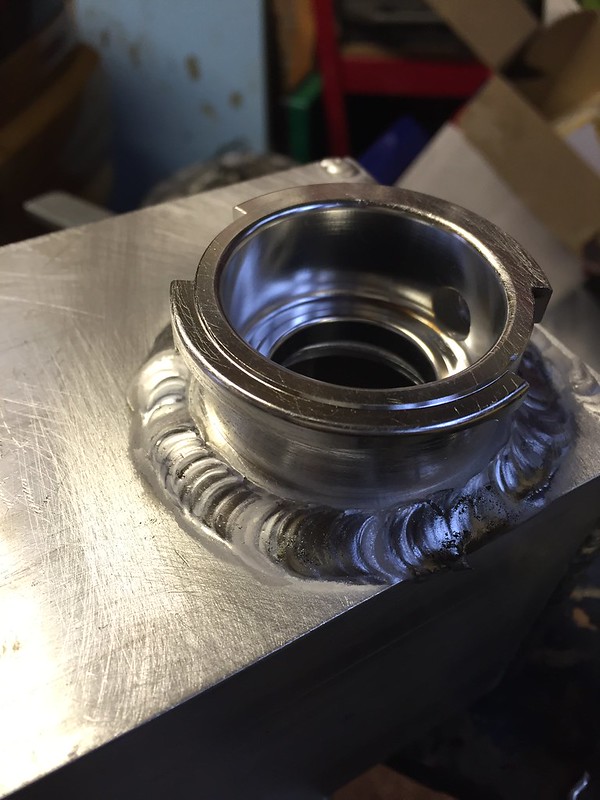 IMG_4726 by Steve Count, on Flickr IMG_4726 by Steve Count, on FlickrIt's going to fit where the power steering reservoir would normally sit, with the outlet going down where the screen wash filler neck would be, into a tee piece that i'll fit into the bottom radiator hose. On the back wall i'll fit two hose tails, one for the radiator and the other which will go to a banjo fitting that now lives in the bleed point in the thermostat housing. Tomorrow i think i'll look into mounting the Laminova, radiator fans and intercooler, then maybe dry plumbing it. The rest of the intercooler pipework has been ordered and should be here next week, just a few bits left to buy now. I was going to try and keep the standard ecu but having tried and failed to get in touch with wayne, and after a little gentle persuasion from Allan i'm now looking to get an aftermarket ecu. I've never had anything to do with them in the past so i'll probably try making up my own loom, the only thing i'm not sure about is whether things like the oil level gauge/temp sensor will work with aftermarket ecu's? Would be quite handy if they did as i like to keep an eye on the oil level before starting, and obviously keep track on oil temps when on track, especially now i'll have a new cooler i want to see how that will affect things without having to shell out for another gauge. ________________________________________ Goldie the track car. |
|
|
|
 prism7guy prism7guy
Seasoned Pro Location: DoncastAAAAARGH Registered: 13 Jan 2008 Posts: 4,640 Status: Offline |
Post #536
Oh yeah, i've also decided to do away with the charcoal cannister, and now that i'll be using a different inlet manifold i think i'll have to make some sort of oil catch tank.I've done a bit of reading on here and there seem to be quite a few mixed opinions on how to fit them, i think i'm going to go down the route of connecting one inlet to the 25mm port on the block to the right of the oil filter, one to the head where the normal hose that would connect to the above mentioned 25mm hose would go to, then have like a breather hose that may run under the car somewhere with a breather fitted. Is it acceptable to just block up the other outlet from the cam cover, and is the way i've mentioned above the best way to do it? ________________________________________ Goldie the track car. |
|
|
|
 pete_rallye pete_rallye
Seasoned Pro Location: Yorkshire Registered: 12 Dec 2002 Posts: 5,253 Status: Offline |
Post #537
The way I have usually seen it done is use the standard big hose from the bottom block take off to middle right hand side t-piece to the top of the cam cover, but put it on the inside take off, rather than the outside one. Then just run one hose to the catch tank from the outer cam cover take off. Then everything breathes thru the one hose and keeps it simpler and tidier. Longmans used to recommend having a drain hose from the bottom of the catch tank to (what would be) the oil level sender hole which would then allow additional breathing for the block, and also empty the oil back into the sump as you catch it, but tbh, I'm not convinced its necessary! ________________________________________ Oulton Park in a BTCC 306 vid 1Oulton Park in a BTCC 306 vid 2 Lap of the 'ring |
|
|
|
 prism7guy prism7guy
Seasoned Pro Location: DoncastAAAAARGH Registered: 13 Jan 2008 Posts: 4,640 Status: Offline |
|
|
|
|
 Day666 Day666
Seasoned Pro Location: Bristol Registered: 20 Apr 2013 Posts: 5,214 Status: Offline |
Post #539
Looks amazing & bloody good Alloy welding  I've done quite a lot of Alloy & Stainless welding myself & your defo doing really well  Keep up the great work & updates as it's a brilliant read  |
|
|
|
 prism7guy prism7guy
Seasoned Pro Location: DoncastAAAAARGH Registered: 13 Jan 2008 Posts: 4,640 Status: Offline |
Post #540
Thanks Damien  I got a bit more done today, i mounted the header tank. It's going to be a bit of a nuisence connecting the indicator wire when i remove/replace headlights but i'm sure i'll sort something out.  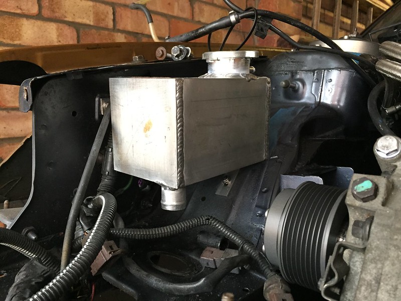 IMG_4734 by Steve Count, on Flickr IMG_4734 by Steve Count, on FlickrNext up i mounted the laminova and sorted the top coolant hose routing.  IMG_4739 by Steve Count, on Flickr IMG_4739 by Steve Count, on FlickrThen sorted out the bottom coolant hose routing etc. Not perfect but it should do the job i hope.  IMG_4736 by Steve Count, on Flickr IMG_4736 by Steve Count, on FlickrFitted the old radiator fans. I had wanted to get bigger ones for higher air flow rates, but it turns out these 10" ones are pretty perfect size wise for the radiator. If the radiator isn't up to cooling everything then i'll look into getting a custom one made up and get bigger fans with that.  IMG_4740 by Steve Count, on Flickr IMG_4740 by Steve Count, on FlickrOne of the last jobs was to make a start on mounting the intercooler. Some of the bumper is going to need cutting away, and some chunks of the slam panel too. The n/s is going to be a pain in the arse though as the boost pipe will want to run right where the inner headlight mounting bolt would go.   IMG_4743 by Steve Count, on Flickr IMG_4743 by Steve Count, on Flickr IMG_4746 by Steve Count, on Flickr IMG_4746 by Steve Count, on FlickrOne other thing that i made a start on today was the inlet manifold. A job i've been dreading if i'm honest as i've read how hard cast ally, especially that which has been exposed to oils etc is to get clean and weld nicely. I'm not sure if i just got lucky or if my preparation paid off. First off i went round each runner with a file to get rid of any crap on the surface. Next i stuck it in my oven for about 30 mins on gas mark 2. No idea what temperature it got to but it was too hot to pick up with bare hands  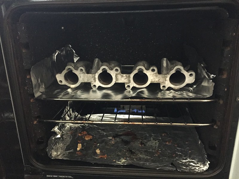 IMG_4730 by Steve Count, on Flickr IMG_4730 by Steve Count, on FlickrI got a couple of old 40mm dia bar ends from the scrap bins at work, turned one end down to 39.5mm dia 10mm in and stuck them in the workmate so they went through the two outer runner holes in the laser cut plate. Next i got the cut down manifold out of the oven and placed it on the plate so that the two bits of 40mm went up the outer runners, this was my way of making sure it was as lined up as i could get it. Then i got a scotchbrite pad soaked in acetone and wiped all the areas to be welded, and after that gave them a quick brush down with a stainless wire brush before any welding took place. I gave each runner a couple of decent tacks to hold it all together, after that i removed the 40mm bar ends and started to weld my way round each runner. I didn't get any photos during the welding, but got a couple of after photos.  IMG_4733 by Steve Count, on Flickr IMG_4733 by Steve Count, on Flickr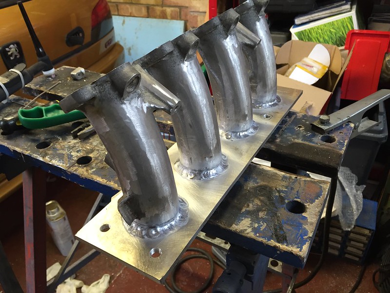 IMG_4731 by Steve Count, on Flickr IMG_4731 by Steve Count, on FlickrI was playing about with the welders settings trying to get a cleaner weld but it seemed pretty impossible to stop the black crap forming in the weld pool. I've read other people have this issue when welding dirty cast stuff so they get a die grinder out then go round and re-weld it all. I don't have a die grinder so i'm just hoping the weld i've got is strong enough to hold it together.  ________________________________________ Goldie the track car. |
|
|
|
 Day666 Day666
Seasoned Pro Location: Bristol Registered: 20 Apr 2013 Posts: 5,214 Status: Offline |
Post #541
Remember if you haven't already before fitting put a perfect straight edge on both ends of inlet inc the opposite end to the welded area ...my reasons are because welding CAN distort everything & you won't get a 100% sill  Looks amazing ...I'm impressed  |
|
|
|
 allanallen allanallen
Seasoned Pro Location: Buxton Registered: 01 May 2007 Posts: 1,399 Status: Offline |
Post #542
Looks like mine!  ________________________________________ www.bridgecraftmotorsport.co.uk |
|
|
|
 prism7guy prism7guy
Seasoned Pro Location: DoncastAAAAARGH Registered: 13 Jan 2008 Posts: 4,640 Status: Offline |
Post #543
It's been a while since i updated this so time for a little update.Too tired to write a lot so i'll just spam this post with mainly pics  Made some trumpets for the plenum  IMG_4772 by Steve Count, on Flickr IMG_4772 by Steve Count, on FlickrMade a start on welding them in position 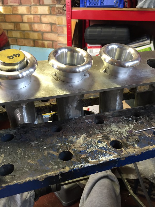 IMG_4812 by Steve Count, on Flickr IMG_4812 by Steve Count, on Flickr IMG_4815 by Steve Count, on Flickr IMG_4815 by Steve Count, on Flickr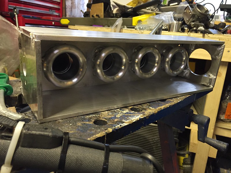 IMG_4822 by Steve Count, on Flickr IMG_4822 by Steve Count, on Flickr IMG_4839 by Steve Count, on Flickr IMG_4839 by Steve Count, on Flickr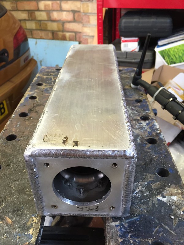 IMG_4836 by Steve Count, on Flickr IMG_4836 by Steve Count, on FlickrMounted the remote filter adapter  IMG_4851 by Steve Count, on Flickr IMG_4851 by Steve Count, on FlickrMade some oil lines  IMG_4852 by Steve Count, on Flickr IMG_4852 by Steve Count, on FlickrMocking up the boost pipework  IMG_4845 by Steve Count, on Flickr IMG_4845 by Steve Count, on Flickr IMG_4848 by Steve Count, on Flickr IMG_4848 by Steve Count, on FlickrBought some rubber sheet to make my own gaskets  IMG_4844 by Steve Count, on Flickr IMG_4844 by Steve Count, on FlickrMade a new live junction box type thing for the engine bay, prefer this to linking everything to the starter motor.  IMG_4841 by Steve Count, on Flickr IMG_4841 by Steve Count, on FlickrEmptied as much of the old 95 ron fuel as i could  IMG_4855 by Steve Count, on Flickr IMG_4855 by Steve Count, on FlickrMounted an oil catch tank  IMG_4856 by Steve Count, on Flickr IMG_4856 by Steve Count, on FlickrRemoved the old fuel pump/sender unit  IMG_4858 by Steve Count, on Flickr IMG_4858 by Steve Count, on FlickrDidn't fancy using the standard high pressure pump to act as a lift pump for a swirl pot, plus i'm not convinced it's running perfectly as the car often cuts out shortly after firing it up, then the pump will re-prime again. I tried the relay from my other gti6 which works fine and the same problem persisted. May have been some other electrical issue but i never got to the bottom of that. I've bought a facet low pressure pump to act as a lift pump to the swirl pot, and a walbro from ash to act as my main high pressure pump to the rail. Bought a 2 litre swirl pot off ebay, not the nicest thing in the world but it was cheap and came with plenty of useful bits to make the whole lot cheaper. Cut off the top of the old pump and used some hose to link that to the one way valve at the bottom of the housing.  IMG_4860 by Steve Count, on Flickr IMG_4860 by Steve Count, on Flickr IMG_4859 by Steve Count, on Flickr IMG_4859 by Steve Count, on Flickr IMG_4861 by Steve Count, on Flickr IMG_4861 by Steve Count, on Flickr IMG_4863 by Steve Count, on Flickr IMG_4863 by Steve Count, on Flickr IMG_4864 by Steve Count, on Flickr IMG_4864 by Steve Count, on FlickrBack together  IMG_4865 by Steve Count, on Flickr IMG_4865 by Steve Count, on FlickrSwirl pot mounted 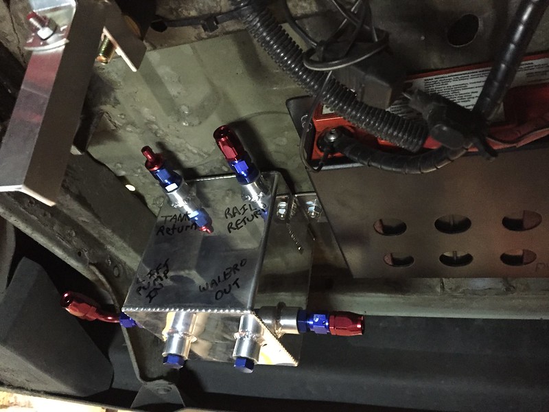 IMG_4872 by Steve Count, on Flickr IMG_4872 by Steve Count, on FlickrMade a kind of subframe to mount the two pumps and filters etc to. That's held to the car with two m8 and one m6 rubber anti vibration bobbins, hopefully they will damp out the annoying noises pumps tend to make, not that i'd hear them over the exhaust anyway   IMG_4877 by Steve Count, on Flickr IMG_4877 by Steve Count, on FlickrSince these photos were taken i've secured the braided lines to the car along the run where the standard lines would run, just using rubber lined P clips and the holes used for the plastic line holders. I've also ran new wires to power the pumps from the bulkhead along the fuel lines inside some convoluted conduit. Tonight i did most of the an fittings on the fuel lines and connected it all up but i forgot to take photos. Allan took me up the hill at pugfest in his eaton charged 205 last weekend, it was epic and now i can't wait to get this finished and mapped.  The last of my parts have been anodised and can be picked up after work tomorrow, so hopefully there will be another update soon enough.  ________________________________________ Goldie the track car. |
|
|
|
 pete_rallye pete_rallye
Seasoned Pro Location: Yorkshire Registered: 12 Dec 2002 Posts: 5,253 Status: Offline |
Post #544
Seriously good work, can't wait to see the end result of this, really good to see people trying new stuff too. ________________________________________ Oulton Park in a BTCC 306 vid 1Oulton Park in a BTCC 306 vid 2 Lap of the 'ring |
|
|
|
 eddy_gti6 eddy_gti6
Seasoned Pro Location: Durham Registered: 20 Oct 2008 Posts: 8,716 Status: Offline |
Post #545
Good work. Nice tidy job, when you going to be selling your own parts?  wouldnt mind one of them header tanks wouldnt mind one of them header tanks________________________________________ Clicky: [url =http://www.306gti6.com]click here[/url] remove the space between [url & = |
|
|
|
 rallyeash rallyeash
Seasoned Pro Location: Devizes Registered: 11 Dec 2006 Posts: 4,424 Status: Offline |
Post #546
Fantastic work Steve. ________________________________________ 230 hp 2.1 16v XU 205 rallye on jenveys Project thread here Project thread here309 3dr K20 Type R |
|
|
|
 jeffers
Forum Admin jeffers
Forum AdminLocation: Leeds Registered: 14 Dec 2003 Posts: 3,702 Status: Offline |
Post #547
Top work Steve, really lookin forward to seeing this in action!  ________________________________________ Team Running Engine again!Team Negative Camber! My Budget track engine build thread! Now appearing at a Trackday near you!!   |
|
|
|
 prism7guy prism7guy
Seasoned Pro Location: DoncastAAAAARGH Registered: 13 Jan 2008 Posts: 4,640 Status: Offline |
Post #548
Thanks for the compliments lads  No plans to start selling my own bits just yet Chris, and to be honest i couldnt compete with the cost of some of the header tanks on ebay with the amount of time i put into mine, and purely the cost of sourcing the parts for it like the box section, pressure cap bit and beaded tubes to weld on added up to similar to what others are selling theirs for! Small update time again, i got my anodised parts the other day.  IMG_4948 by Steve Count, on Flickr IMG_4948 by Steve Count, on Flickr'Charger plate mounted  IMG_4951 by Steve Count, on Flickr IMG_4951 by Steve Count, on FlickrStarted stripping the charger for a closer look for any damage/wear, gave it a good clean and gave it some fresh oil.  IMG_4949 by Steve Count, on Flickr IMG_4949 by Steve Count, on Flickr IMG_4950 by Steve Count, on Flickr IMG_4950 by Steve Count, on FlickrThat's now back together and mounted. I finished off the fuel lines, only the two fittings to fit for the new rail but i wanted to just push the current ends over the old rail to make sure i could get the car running again and get it running up to temperature, mainly to ensure i don't have any leaks as it's all new fuel system, oil cooling system and coolant system. I took the plugs out and cranked it over for a while to get some oil round the engine, refitted the plugs and coilpacks, topped back up with oil, fitted the old ecu and cranked it over. It fired up without too much drama but was idling around 3000rpm and fluctuating. I turned it off then removed the ICV from the plenum and sealed that hole, and tried again. This time it was idling around 2500rpm so i left it at that and went to investigate what it was. Turns out it was a couple of airleaks around where the manifold meets the head, i kept spraying brake cleaner at it and this affected the revs so i went round nipping up the capscrews/nylocs until it settled down to a nice 1000rpm. I bought a 5mm thick ptfe gasket from ebay (thermatec rings a bell, really helpful bloke!) as i knew the manifold mating face had warped with all the welding, so i bought it plenty thick enough to compress and create a good seal, i also fitted a new paper style gasket between the ptfe gasket and the manifold in the hope it would create a better seal.  IMG_4952 by Steve Count, on Flickr IMG_4952 by Steve Count, on FlickrThats about it for now. I've got a DTA E48 ecu to fit for the conversion, but at the moment i'm having some connection issues with it and my computer, just ordered a pcmcia-serial card so hopefully that will rule out the usb-serial cable being the issue as i dont know what chipset it has and it was an old ebay special, with a lost driver cd  ________________________________________ Goldie the track car. |
|
|
|
 Chr1sch Chr1sch
Seasoned Pro Location: Worcester Registered: 02 Aug 2014 Posts: 1,025 Status: Offline |
Post #549
Just wow, well done sir those are some epic skills! |
|
|
|
 eddy_gti6 eddy_gti6
Seasoned Pro Location: Durham Registered: 20 Oct 2008 Posts: 8,716 Status: Offline |
Post #550
Any more updates on this steve?________________________________________ Clicky: [url =http://www.306gti6.com]click here[/url] remove the space between [url & = |
|
|
|
The Peugeot GTi-6 & Rallye Owners Club - ©2024 all rights reserved.

Please Note: The views and opinions found herein are those of individuals, and not of The Peugeot 306 GTi-6 & Rallye Owners Club or any individuals involved.
No responsibility is taken or assumed for any comments or statements made on, or in relation to, this website. Please see our updated privacy policy.